The Mespelare Decision Matrix
 In the previous articles we’ve ran the modified firmware for our Mespelare module for the first time. In this article we’ll play with the Decision Matrix so we can make the module respond to events on the bus.
This article is a draft and is not finished yet. Proceed at your own peril.
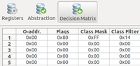
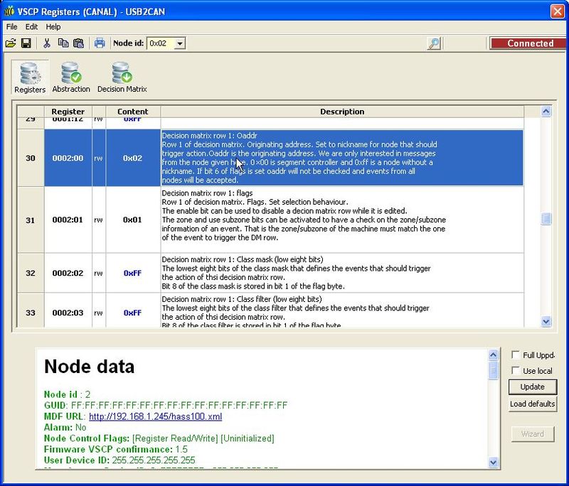
The DM is configured in the registers starting at 0002:00 (line 30). The descriptions in the MDF and the VSCP specification explains what each register configures.
Another good read to prepare for the following is How filter/masks work.
We will change the following register values:
- 0002:00 (oaddr): we will set this to 0x02 (the module’s own address) so that our DM reacts to events from our own module. This means our events will be handled locally on the board for now, and we won’t involve any other modules just yet.
- 0002:01 (flags): we’ll set the following flags:
- bit 7 (row enabled): we’ll set this to 1 so that this row of the DM is enabled.
- bit 6 (match oaddr): we’ll set this to 0 so that the module will respond regardless of what module has sent the event.
- bit 5 (hard-coded oaddr): not quite sure what this does, we’ll set it to 0.
- bit 4 (match Zone): we’ll set this to 1 to enable Zone matching.
- bit 3 (match Sub-zone): we’ll set this to 1 to enable Sub-zone matching.
- bit 2 (reserved): we’ll leave it as-is (0).
- bit 1 (class mask bit 8): this bit is not a flag, but rather the 9th bit of the class mask. As you can see below, it’s value is 1.
- bit 0 (class-filter bit 8): this bit is not a flag, but rather the 9th bit of the filter. As you can see below, it’s value is 1.
- Combining the above bits, the flags registers’ value is 0x9B
- 0002:02 (class mask): we’ll set this to 0xFF to pass all bits in the filter.
- 0002:03 (class filter): we’ll set this to
..to be continued..